My Account Shop all Stair Treads Stringers Cladding Smart LED Lights Fitting Accessories Balustrades Newel Posts Joinery Parts Flooring Doors Fitters 👷‍♂️ Trader Club Careers Clearance
🚚 Delivery within 5 to 10 working days.

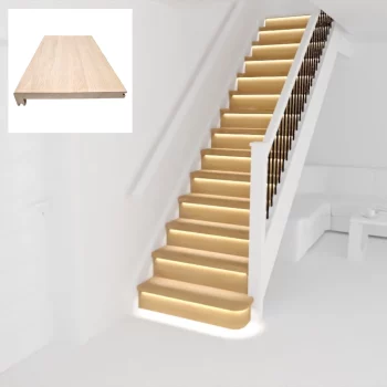
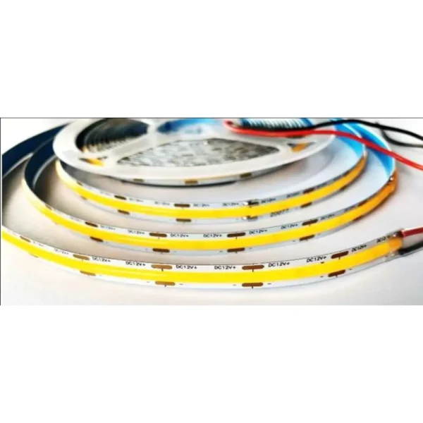
Smart CoB LED Stair lighting Bundle V5-20 – Warm White

£472.26
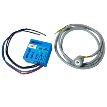
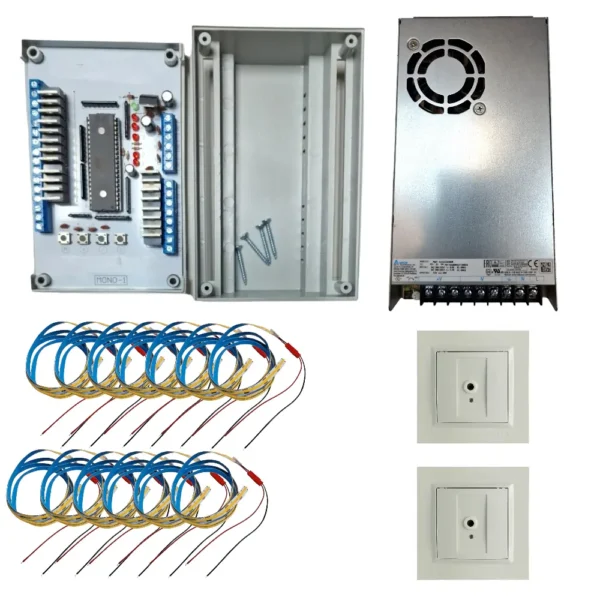
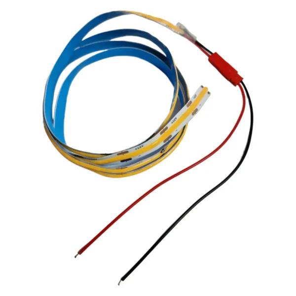
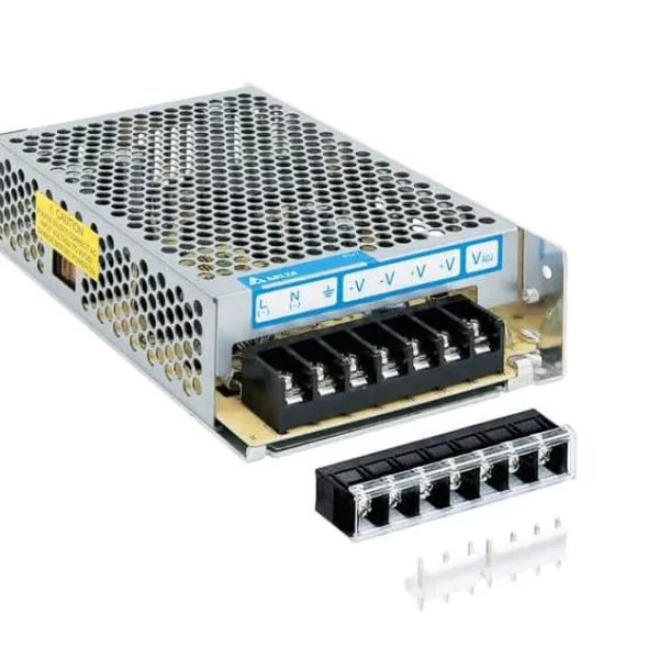
The below default items and quantities should be sufficient for the proposed bundle :
£216.10

In stock and ready for dispatch

+
£52.19

In stock and ready for dispatch

+
£49.39

In stock and ready for dispatch

+
£35.06

In stock and ready for dispatch

+
Before adding to basket, please ensure the selection matches your requirements. Your selected items will be added to the basket individually.
SKU:

Specification Instruction (PDF) WARNING When installing the controller, be careful: to correctly connect the +12 V and -12V wires; reversing the connection can damage the processor. when the controller is on, do not touch the circuit board on the solder points side – this can cause a surge and damage the processor. when the controller…

Description

Specification Instruction (PDF)

WARNING

When installing the controller, be careful:

  • to correctly connect the +12 V and -12V wires; reversing the connection can damage the processor.
  • when the controller is on, do not touch the circuit board on the solder points side – this can cause a surge and damage the processor.
  • when the controller is on, do not touch wires to the backs of passive and active components – this can cause a surge and damage the processor.
  • do not connect +12V voltage to the controller channels or to the PD, PG, PS sockets – this can cause a surge and damage the processor.

  1. Correctly connect the (-) LED strips, LED bulbs, etc. to the appropriate channel of the stair controller (step 1 to channel 1; step 2 to channel 2, etc.).
  2. Connect all the (+) LED strips, LED bulbs, etc. together – then connect them to the (+12V – LED power supply).
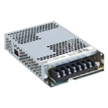
  3. Properly connect the 230/12V power supply to the stair controller (make sure to connect -12V to the -12V socket and +12V to the +12V socket).
  4. Create a jumper on the socket marked PS, then connect the 230V power supply – if the installation is done correctly, all lights will turn on.
  5. Turn off the power, remove the PS jumper.
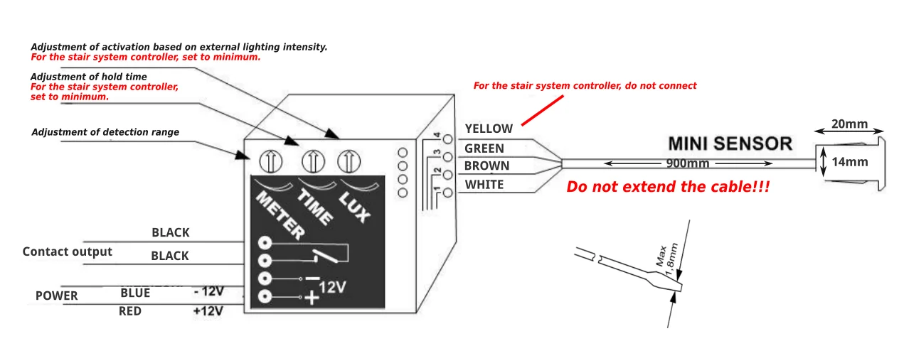
  6. Connect the motion/twilight sensors – sensors should ideally be installed 25-35 cm above the ground; after installation, please check the voltage reaching the sensor. It should be a minimum of 12V, preferably 12.05V (for “white” sensors, after connecting the cables, close the sensor as it will not function correctly if left open).
  7. Programme the controller according to the instructions without skipping any steps.

Intelligent Stair Controller – version 5-20 light points

Basic technical data:

  • Supply voltage: 8-15V DC. Typically 12V DC.
  • Current consumption by the controller alone: 20mA.
  • Power consumption by the controller alone at 12V supply voltage: 0.25W.
  • Load capacity: up to 1A per channel (step).
  • Operating ambient temperature: 5-35 °C.

Controller description:

  • Buttons (micro-switches) “M”, “+”, “-“, “S” – programming buttons
  • PS – continuous lighting input (all light points light up when shorted)
  • PG – short-circuit input for the top-down sensor
  • PD – short-circuit input for the bottom-up sensor
  • Inputs 1 – 20 – inputs for subsequent channels
  • “-12V” – negative power supply input
  • “+12V” – positive power supply inputs

Algorithm (controller functions):

  • Movement control on the stairs from top to bottom
  • Movement control on the stairs from bottom to top
  • Control of movement with mutual climbing of the stairs (one user from the top, another user from the bottom)
  • Step-by-step or smooth operating mode
  • Adjustment of light point ignition time (from 0.25 seconds to 5 seconds)
  • Adjustment of light point extinguishing time (from 10 seconds to 3 minutes)
  • Various modes of operation in standby state:
    • Mode – “nothing lights up”
    • Mode – the extreme light points light up
    • Mode – all light points light up
  • Adjustment of the brightness of light points in standby state (within 0 to 50% of the light source power)
  • Continuous lighting function
  • Half-landing movement support (via continuous lighting function)

Sequential ignition and extinguishing.
Before the effect reaches the end and the second sensor is activated, there will be an “opposite” effect, and two effects will meet along the way (the controller will recognise that a second person has entered the stairs from the opposite side). If the effect reaches the end and the second sensor is triggered, the controller recognises that the person is leaving the stairs and will signal extinguishing in the same direction as the ignition (one person was on the stairs, entered and left).

Programming

Entering programming mode:

  1. Turn off the 12V DC power to the controller.
  2. Press and hold the “M” micro-switch.
  3. Turn on the 12V DC power to the controller.
  4. Entering programming mode will be indicated by three flashes of the LEDs from 1 to 5.
  5. The controller enters programming mode; the first step is programming the number of steps (light points).

Programming the number of steps (light points) – no LED lights up:

  1. The default number is 5 light points.
  2. The selected number of light points is indicated by LED 2 (the number of flashes corresponds to the number of set light points).
  3. After entering programming mode, use the buttons (micro-switches) “+” and “-” to select the desired number of light points (steps). Each press of the button triggers a sequence of the LED; wait for it to finish before pressing the button (micro-switch) again.
  4. Confirm the number of steps (light points) with the “S” button (micro-switch).
  5. After pressing the “S” button, proceed to programming the operating mode.

Programming the operating mode (step-by-step or smooth) – LED 5 lights up:

  1. The default is set to smooth operation mode.
  2. Pressing the “+” button (micro-switch) selects the step-by-step operation mode (visualised by LED 1).
  3. Pressing the “-” button (micro-switch) selects the smooth operation mode (visualised by LED 1).
  4. Confirm the operating mode with the “S” button (micro-switch).
  5. After pressing the “S” button, proceed to programming the step (light point) ignition speed.

Programming the step (light point) ignition speed – LED 4 lights up:

  1. The user can choose from 20 ignition times from 0.25 seconds to 5 seconds – each press of the “+” or “-” button (micro-switch) changes the setting by 0.25 seconds.
  2. Pressing the “+” button (micro-switch) lengthens the ignition time (visualised by LED 1).
  3. Pressing the “-” button (micro-switch) shortens the ignition time (visualised by LED 1).
  4. Confirm the ignition speed with the “S” button (micro-switch).
  5. After pressing the “S” button, proceed to programming the lighting duration of the steps (light points) after the user passes.

Programming the lighting duration of the steps (light points) after the user passes – LEDs 4 and 5 light up:

  1. The default is set to 10 seconds. The user can change this value from 10 seconds to 3 minutes. Indication is by LED 1 – each flash adds 10 seconds (from 1 to 18 flashes).
  2. Pressing the “+” button (micro-switch) lengthens the lighting duration of the steps after the user passes (visualised by LED 1).
  3. Pressing the “-” button (micro-switch) shortens the lighting duration of the steps after the user passes (visualised by LED 1).
  4. Confirm the lighting duration of the steps (light points) after the user passes with the “S” button (micro-switch).
  5. After pressing the “S” button, proceed to programming the controller’s behaviour in standby mode (when no one is on the stairs).

Programming the controller’s behaviour in standby mode (when no one is on the stairs) – LED 3 lights up:

  1. The controller has 3 standby modes (default mode “a”) (indicated by LED 1): a. No light points light up (one flash of LED 1). b. All light points light up (with the set light source power) (two flashes of LED 1). c. The extreme light points light up (with the set light source power) (three flashes of LED 1).
  2. Pressing the “+” or “-” button (micro-switch) changes the standby mode.
  3. After pressing the “S” button, proceed: a. to programming the brightness of the light points in standby mode (if option “b” or “c” was selected). b. to end the programming if “a” was selected – to end programming, press the “M” button (micro-switch). Saving to memory is indicated by three flashes of all red LEDs from 1 to 5.

Programming the brightness of the light points in standby mode – LEDs 3 and 5 light up:

  1. The brightness of the light points is visualised by LED 1.
  2. Pressing the “+” button (micro-switch) brightens the light point (visualised by LED 1).
  3. Pressing the “-” button (micro-switch) dims the light point (visualised by LED 1).
  4. Confirm the brightness of the light points in standby mode with the “S” button (micro-switch).
  5. The end of the setting process will be indicated by a single flash of all red LEDs from 1 to 5.
  6. Saving the settings and ending programming is done by pressing the “M” button (micro-switch). Saving to memory is indicated by three flashes of all red LEDs from 1 to 5.

Connecting to a one-sided RESTAN barrier Connect accordingly:

  • terminal 1 – (-12V)
  • terminal 2 – (+12V)
  • terminal 3 (PD or PG)
  • terminal 4 – (PD or PG)


Controller connection diagram


Controller connection diagram


Controller connection diagram


Controller connection diagram


Reviews

There are no reviews yet.

Only logged in customers who have purchased this product may leave a review.

You may also like…